
Trying to build an open source sewing machine - Basics & First Experiments
If you stab someone once, you have to go to court; if you stab something a hundred times, it's called sewing and considered a fundamental cultural technique. I don't know where I am going with this. This blog post is about developing a sewing machine.
You see, there are open designs for 3D printers and open designs for CNC machines. Both helped democratize manufacturing and spawned innovations. However, there are no real open designs for usable sewing machines. I believe developing an open design for a sewing machine would be an interesting project in mechanical engineering and, of course, a valuable contribution to the overall field of open machine design. I will pursue the goal of developing such a machine, starting by establishing fundamentals and doing first experiments.
What even is a sewing machine?
To understand what I am trying to build, there needs to be a basic understanding of what a sewing machine does.
For anyone vaguely familiar with a sewing machine, you might know that you can pass multiple layers of fabric through the machine, and the sewing machine will sew them together. This is almost always done using a lockstitch. The lockstitch utilizes two threads, an upper and a lower thread. The machine's mechanism intertwines these two threads at every stitch to construct a secure seam. (I will continue to use the handwavy term "intertwine" until I have built up enough fundamentals to better explain what's going on.)
The machine's mechanics can roughly be divided into two parts that work together to construct the seam. The upper part is concerned with moving the needle and handling the upper thread, and the lower part receives the upper thread and intertwines it with the lower thread. A modern sewing machine, of course, has a lot more things going on, which I will briefly touch on later, but these are the two primary mechanisms I am interested in.
Upper mechanism
The simplest sub-mechanism in the upper part is the one that moves the needle up and down. It's a simple slider-crank mechanism that links the needle bar, which is constrained to up and down movement, to the rotary movement of the motor. I assume the strength of this mechanism is the main factor that influences if a sewing machine can pierce 10 layers of denim or just two layers of thin cotton.
Also linked to the rotary movement of the motor is the return arm, which pulls up the upper thread every cycle after it is intertwined with the lower thread. I was only able to deduce that the mechanism is some kind of four-bar linkage that is combined with the slider-crank linkage for the needle bar. I definitely could have researched the basic mechanics better, but I didn't and simply copied an established design. More on that later.
The third integral part of the upper mechanism is the thread tensioner. The thread tensioner is nothing more than two discs held together by a spring with adjustable tension. The thread passes from the thread spool through the tensioner, through the return arm, and finally through the eye of the needle. The tension of the thread as controlled by the thread tensioner also influences how the two threads are intertwined.
Lower mechanism
The whole job of the upper mechanism can be summed up as pushing the needle with the upper thread through the fabric and presenting it to the lower mechanism. The lower mechanism's job is then to do the intertwining. The lower thread is kept on a bobbin that is relatively small compared to the whole spool of upper thread.
When the upper thread is pushed through the fabric by the needle and the needle starts to retreat, a small loop of upper thread forms at the needle, because the upper thread doesn't move back as fast as the needle (because the smooth needle differs from the rougher thread in friction (I assume)). This little loop can now be exploited by a mechanism that does the intertwining.
In older machines this was done by moving the bobbin in a bobbin case back and forth through this loop. Forward in one cycle through the loop and then backwards in the next cycle through the next loop. These days the mechanism is more complex. A rotating hook catches the tiny loop in exactly the right moment and passes it around the bobbin case, which sort of floats inside the rotating hook. I don't understand the mechanical details of how this whole design works or even which fields are relevant for designing such a part. I will go in depth regarding the design later in this article.
To sum it up, the lower mechanism's job is to receive the upper thread and somehow wrap it completely around the lower thread every stitch.
Other Features
Besides the described mechanisms, a sewing machine can have a lot of additional features. Almost all sewing machines have some kind of presser foot that holds the fabric in place while sewing.
Likewise, most sewing machines have a transport mechanism for moving the fabric. Often the mechanism is a so-called feed dog that moves forward every time the needle is not in the fabric. The movement of the feed dog dictates the distance between individual stitches. It is also possible that the presser foot or the needle moves the fabric.
A lot of sewing machines not only allow for the fabric to move forward and backward automatically but also for the needle to move left and right. This allows machines to generate more complex stitches, such as zig-zag stitches.
A reference sewing machine
Now that it is understood what a sewing machine does, I want to sketch out my vision for an open-source sewing machine.
I envision a design that implements the basic functionality of a sewing machine. For now that means building a working upper and lower mechanism. I believe this is what a sewing machine is mainly about and where the real design complexity is. I think building a presser foot will be trivial, and designing a feed dog is also not that hard. I am also most interested in utilizing my design to build an embroidery machine, so I don't need either of these components. My understanding of my design goal is not to provide a fully working sewing machine, but more like a reference implementation that can be built upon.
While trying to stay true to most of the classic elements of a sewing apparatus, my aim is to deviate in one crucial point. Most sewing machines have one motor, and the lower and upper mechanisms are linked via belts. I think separating the two mechanisms and having a powerful DC motor for the upper mechanism and a stepper for the bottom mechanism might be an interesting thing to try. The lower stepper simply tracks the position of the upper motor via an absolute encoder and turns accordingly. This allows one to build sewing machines with virtually unlimited long arms, making the handling of extremely large sheets of fabric feasible. I think this could open up interesting new possibilities. On the downside, it, of course, introduces complexity in the electrical engineering and software domain.
After all this theory, it's time to get started designing. I don't have a lot of experience with mechanical design, but the upper mechanism seemed simpler (easier to copy) to me, so I started out with that one.
Building the upper mechanism from scratch
When I first set out to design the upper mechanism, I didn't realize that it is basically a slider crank mechanism mixed with a four-bar linkage. So I searched for a mechanism that I could completely copy instead of understanding the mechanics and designing it from scratch.
I found this article:
Safak S, Saka Z, Ozcelik Z. "Modification of the Classical Needle Bar and
Thread Take-Up Lever Mechanism in Sewing Machines."
FIBRES & TEXTILES in Eastern Europe 2012; 20, 4(93): 108-111.
Public Access Link
The article discusses design issues with the prevalent design of sewing machines and introduces a new design. There were a lot of illustrations in the article, but sadly no full set of measurements to rebuild the mechanism. I used Claude Opus to retrace the steps in the paper and build a solver in Python, just like the authors, to get to the results the authors omitted from their paper. I exported the resulting mechanics as a DXF file and imported it into Fusion 360. So, up to this point, I got the mechanical design of an upper mechanism without much thinking on my part.
In Fusion 360 I first did a design just for testing the mechanics, using the simulation tools inside Fusion 360. The results seemed promising.
After verifying the mechanical basics, I build a design for manufacturing. I had only built mechanisms with standard roller bearings before, so I needed to expand my toolbox a little. For the rotary joints I used sintered bronze bushings and little metal pins. I used 3D printing to create the linkages. I fixed the pins and bushings to the linkages using an interference fit. To lock the pins in place, I used lock washers, but that worked horribly, because the lock washers would have needed a groove in the pins that I was unable to manufacture. I also used PTFE washers between the lock washers and the bushings, but because the lock washers didn't fit properly, that also went nowhere.
Instead of using a motor to run the whole thing, I simply mounted the main wheel on a ball bearing so it could be turned by hand.
The needle rod is also fixed in a bronze bushing for smooth linear motion.
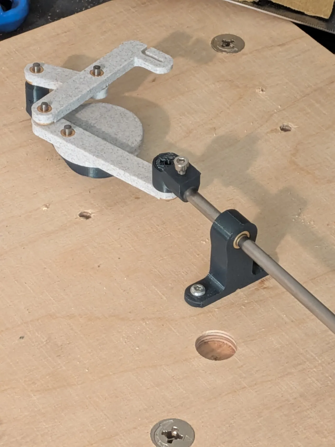
I assembled the whole design and mounted it to a wooden plate. One can turn the main wheel and understand how all the components move. However, the thing can't be used for real sewing. There is too much friction in the whole assembly. I believe there are several issues that contribute to the immense friction and which all need to be addressed.
I believe the first issue is how I used the bushings. Not only do they have contact with the pins they rotate around, but they also have large areas of contact with the washers or other linkages. I looked at a real sewing machine, and I got the impression that they had done everything possible to minimize these contact areas. I think it would be wise to disassemble a real sewing machine and analyze exactly how the mechanism is built there. I believe I should also read up on the proper usage of bushings in designs.
Related to the use of the bushings are the pins and the lock washer. The whole thing simply didn't work. I need to either get a lathe to manufacture better pins with grooves or find some other solution to fix the pins.
Lastly, the needle rod had immense friction in its bushing. I bought the bushings first and selected bushings with a 5 mm inner diameter because my sewing machine had a 5 mm needle rod. However, I wasn't able to find 5 mm rods with appropriate precision and surface finish. I will try to rework the stainless steel rods I utilized and see if I can easily grind them smoother and otherwise try to find better rods.
And because I probably have to redo the whole design anyway, I will look into both slider crank and four-bar linkage theory to see if I can design my own mechanics from scratch, without copying the paper.
So in theory I got a working mechanism, and in practice I got a mechanism that demonstrates the theory but won't work in any real application.
Copying the lower mechanism from an existing machine
This is the part where I am totally flying blind. While the theories of mechanics and the practical knowledge for building the upper mechanism are certainly out there, I don't even know which basics to look up to build a lower mechanism from scratch.
So I opted to analyze the mechanism in my existing Brother sewing machine as close as possible and sort of reverse engineer it. It went horribly. While I ended up with a mechanism that once again demonstrates the idea, there is no way I will ever get to a usable design with 3D printing. The tolerances and the surface finish for reliable and smooth operations are not there. The parts rub too much against each other, and the thread gets stuck on the rough texture of the parts' layer lines.
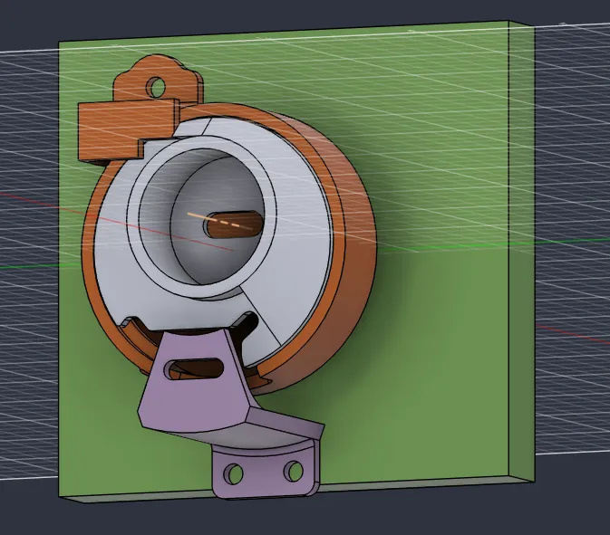
I think both 3D printing as a manufacturing technology and mindlessly copying an existing design are dead ends. I will try to research if I can find fundamentals regarding the design of this or similar mechanisms. Alternatively, I will see if I can come up with other mechanisms (maybe more electromechanically minded) that allow me to stick 3D printing as the principal manufacturing technique.
Conclusion
I introduced the basic workings of a sewing machine and my vision for an open-source sewing machine design, which I imagine to be a kind of reference design, that new designs can be based upon.
I took first shots at designing all necessary components for a basic sewing machine. I was able to theoretically verify a design for an upper mechanism but failed in constructing it. I tried to copy a design for a lower mechanism but failed in producing something that could be built upon.
I will try to get a manufacturable design for the upper mechanism and will need to find a new starting point for designing a lower mechanism.